
01
Feeding
Bulky or prepared material enters the hopper and is guided toward the cutting chamber at a controlled rate.
Low-speed, high-torque twin-shaft shredding equipment for the coarse reduction of bulky, irregular and difficult recycling feedstock before conveying, secondary crushing, screening or material recovery.
A standalone shredder or the first processing stage of a complete recycling system.
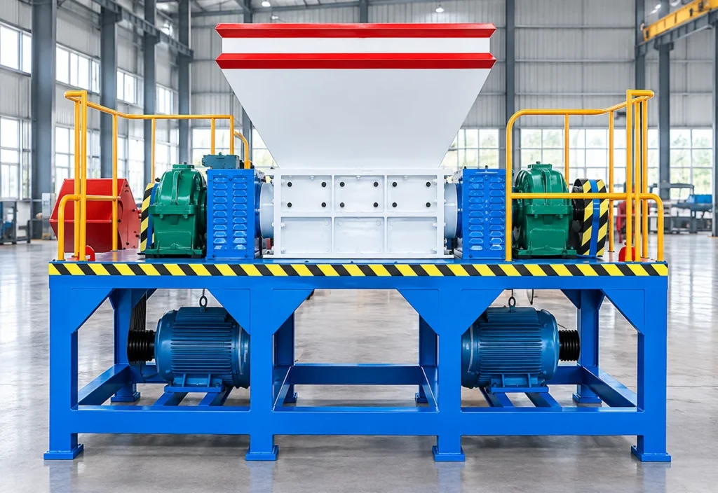
The BREM Double-Shaft Shredder uses two counter-rotating cutter shafts to grip, shear and tear bulky or irregular material into a manageable coarse fraction. It is suited to containers, appliances, pipes, pallets, tires, selected scrap metal, RDF and other compatible waste streams. The welded steel body, reinforced structure and low-speed high-torque drive are designed for stable industrial operation. Cutter material and geometry should be selected according to feed composition, size, abrasiveness and the required downstream result.
Model size alone does not determine suitability. Feed dimensions, material composition, steel thickness, contamination, required capacity, target output and downstream process interfaces should be evaluated together.
02 / Operating Principle
Material is pulled into the cutting chamber by two counter-rotating shafts. Intermeshing cutters apply low-speed, high-torque shearing force and reduce bulky feedstock into a controlled coarse fraction for downstream processing.
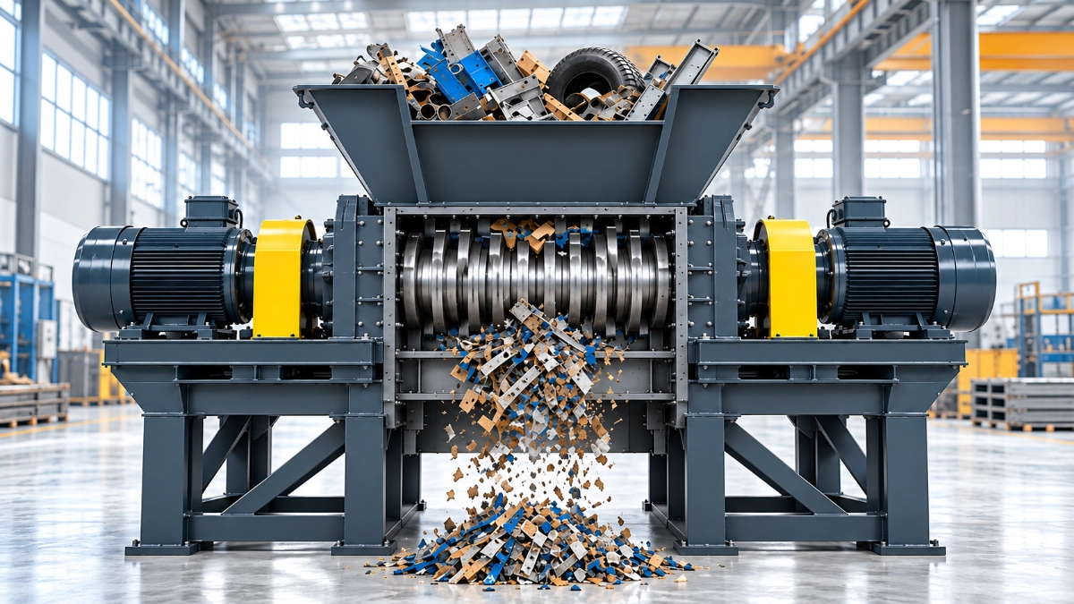
Bulky or prepared material enters the hopper and is guided toward the cutting chamber at a controlled rate.
Teeth on the two counter-rotating shafts catch the material and draw it into the active shredding zone.
Intermeshing cutter discs apply low-speed, high-torque force to shear, tear and open the feed into a coarse fraction.
Reduced material exits the chamber for collection, conveying, secondary crushing, screening or separation.
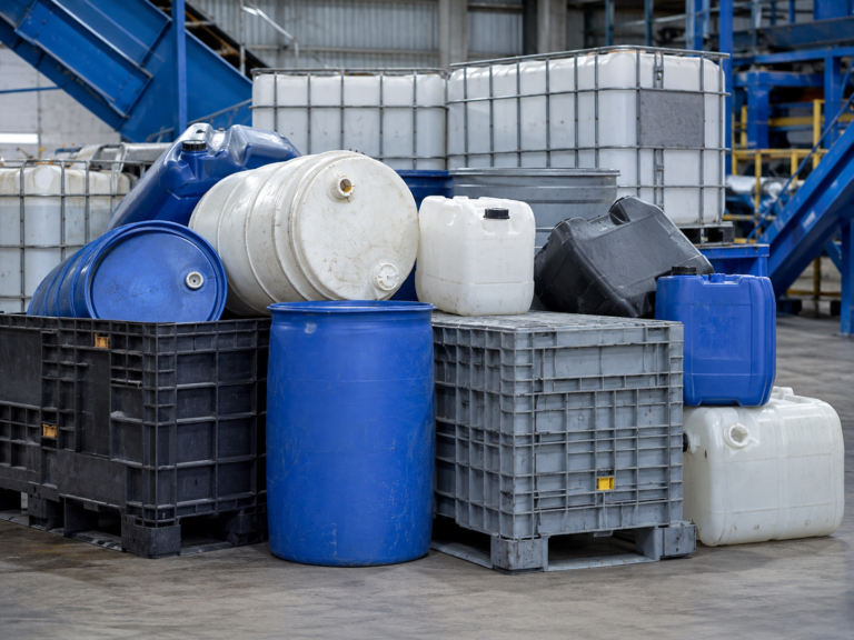
Plastic beverage containers, plastic drums, steel drums, packaging boxes and industrial barrels.
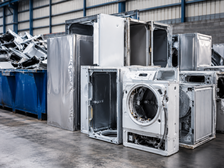
Television, washing-machine and refrigerator housings after suitable preparation.
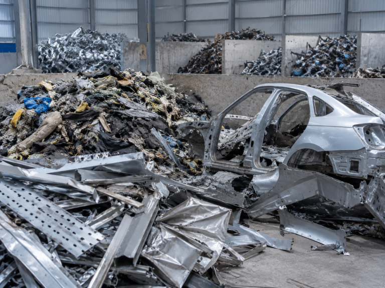
Large pipes, pipe fittings and PE pipe sections suitable for coarse size reduction.
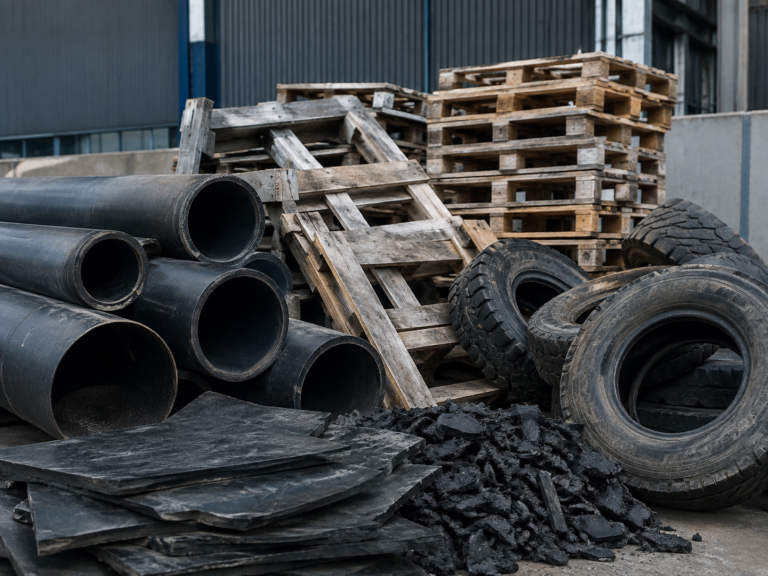
Wood pallets, plastic pallets and forklift pallet boards.
Passenger-car tires and truck tires, subject to model and cutter selection.
Automotive shells, aluminum alloy, cast-aluminum scrap, engine housings, lead and steel plate up to approximately 5 mm as stated in the source material.
Kitchen waste, household waste, animal carcasses, RDF-derived material, medical waste, biomass straw and garden waste; project-specific pretreatment and compliance confirmation required.
Rubber head/offcut material and paper-mill twisted rope or pulper rope.
04 / Machine Architecture
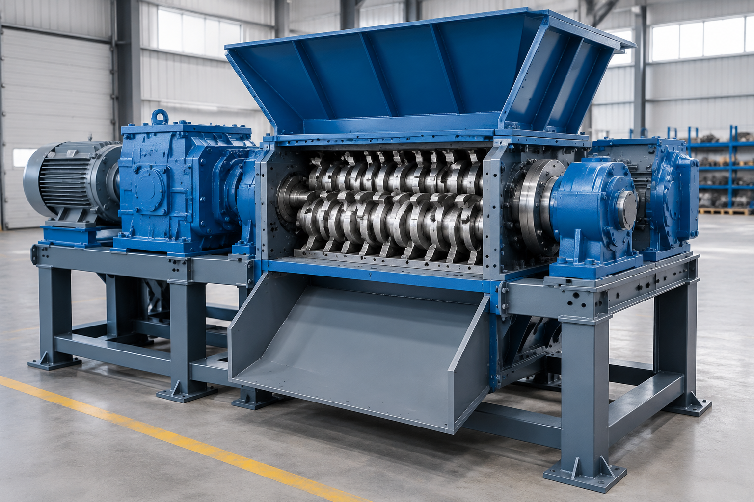
Receives bulky feed and guides it toward the cutting chamber.
Counter-rotate to grip and pull material through the active shredding zone.
Apply shearing and tearing action for primary coarse reduction.
Converts motor power into low-speed, high-torque shaft rotation.
Carry shaft loads and help maintain stable alignment during operation.
High-strength welded steel structure with reinforcement plates supports operational loads.
Transfers reduced material to collection or the next processing stage.
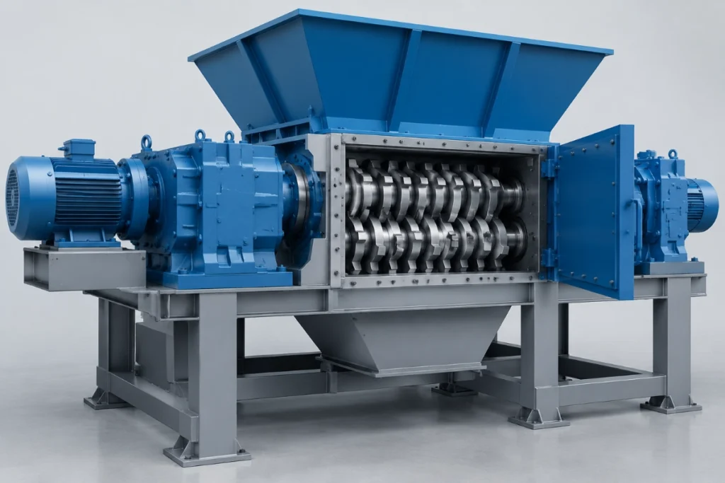
Twin counter-rotating shafts carry intermeshing cutter discs that pull material into the active zone and apply high torque for gripping, shearing and tearing. The welded body and reinforced frame support operational loads, while cutter material and geometry can be selected around different feedstocks and production duties.
| Model | Shaft Speed | Capacity | Cutter Quantity | Cutter Diameter | Output Size | Overall Dimensions | Weight |
|---|---|---|---|---|---|---|---|
| 600 | 18–20 rpm | 2–5 t/h | 26 | 260 mm | 30–100 mm | 2600 × 2000 × 1900 mm | 2500 kg |
| 1000 | 18–20 rpm | 5–10 t/h | 30 | 360 mm | 30–100 mm | 3000 × 2000 × 1900 mm | 5000 kg |
| 1200 | 18–20 rpm | 6–15 t/h | 28 | 372 mm | 30–100 mm | 3200 × 2000 × 1900 mm | 6000 kg |
| 1500 | 14–16 rpm | 8–18 t/h | 30 | 530 mm | 30–100 mm | 4000 × 1700 × 2400 mm | 12000 kg |
| 1900 | 14–16 rpm | 10–25 t/h | 40 | 560 mm | 30–100 mm | 8000 × 2500 × 2400 mm | 15000 kg |
| 2600 | 16–18 rpm | 25–60 t/h | 40 | 720 mm | 30–100 mm | 8200 × 4000 × 4300 mm | 36000 kg |
Actual throughput and output depend on material type, bulk density, feed size, cutter configuration, moisture, contamination and operating conditions. Final model selection should be confirmed against representative feed information.
Coarse reduction of bulky or irregular feed before secondary crushing, screening or separation.
Makes large containers, pipes, pallets, tires and compatible scrap easier to convey and process downstream.
Provides a stable primary reduction stage ahead of crushers, screens and compatible separation equipment.
Reduces suitable bulky waste and RDF-related feed before classification or downstream treatment.
Selection should consider material type and composition, maximum feed dimensions, metal thickness, bulk density, required throughput, target coarse output and downstream process interfaces. A larger model number alone does not guarantee suitability.
Yes. Cutter material, tooth geometry, disc arrangement and related configuration can be selected around the feedstock. The source material specifically states that different cutter materials can be used for different materials to support stable production.
The supplied material list includes hollow containers, appliance housings, pipes, pallets, tires, selected scrap metal, RDF-related waste, garden or biomass waste, rubber offcuts and paper-mill rope. Final suitability must be confirmed against size, composition and contamination.
Yes. The supplied product information states that a feeding conveyor can be configured. Conveyor sizing and control should be matched to the required feed rate, material dimensions and downstream process.
Routine checks should cover cutter wear, fasteners, bearings, shaft supports, gearbox condition, lubrication, chamber cleanliness and abnormal vibration or noise. Maintenance intervals should follow the final machine configuration and operating duty.
No. The 30–100 mm figure is an indicative model-range value from the existing product data. Actual output depends on feedstock, cutter geometry, material behavior and operating conditions, so the target size should be confirmed during equipment selection.
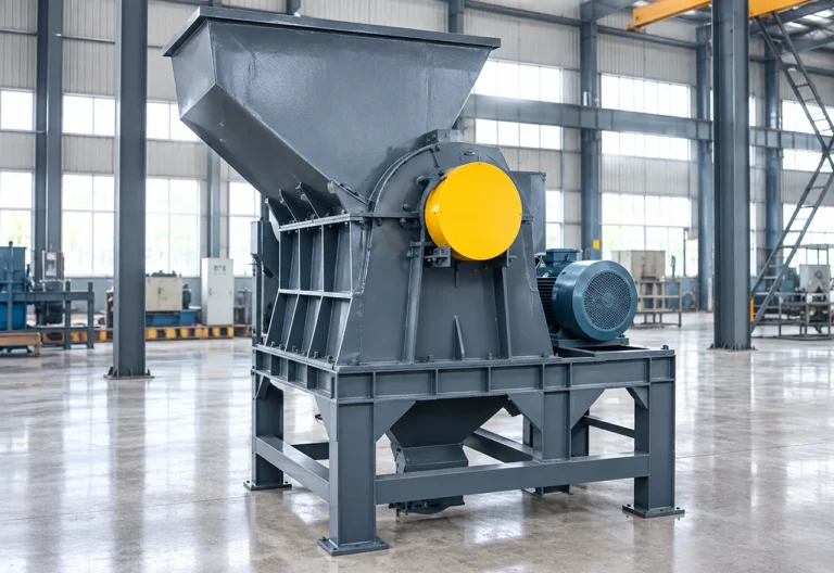
High-speed impact crushing equipment for medium and fine size reduction of brittle and crushable recycling materials such as lithium battery fractions, printed circuit boards,…
View Equipment →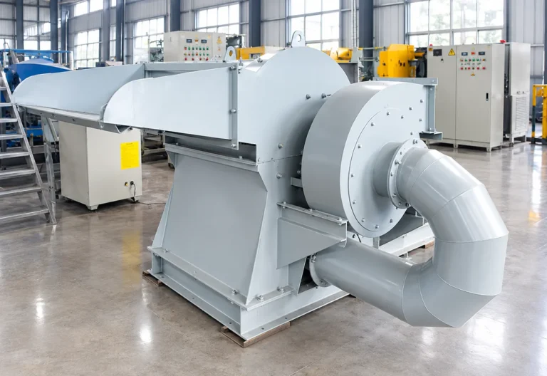
The Industrial Pulverizer is a fine-grinding and material-liberation machine that combines blade-based pulverizing, centrifugal regrinding, air classification and pneumatic conveying for prepared battery, PCB,…
View Equipment →Share your material type, typical feed dimensions, required capacity, target output size, operating conditions and site electrical information. BREM can review the application and recommend an appropriate machine and cutter configuration.
You can also upload material photos, equipment images, plant layouts or technical documents.
You don't need to know all the technical details. Tell us what you're working with and what you want to achieve, and our team will help you determine the next step.