
01
Contaminated Air Inlet
Contaminated process air enters through the inlet duct and is guided into the first internal treatment chamber.
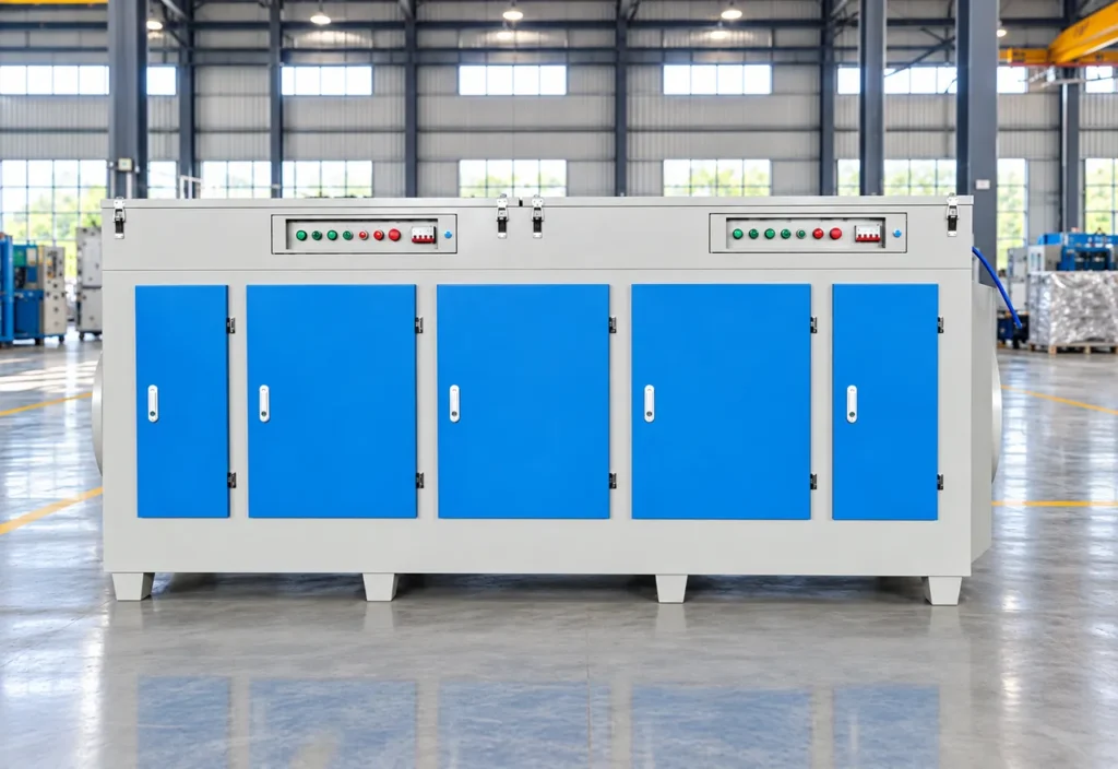
UV Photolysis Purification Equipment is designed for selected industrial exhaust streams containing odor compounds and gaseous organic contaminants. The system uses high-energy ultraviolet radiation to initiate photochemical reactions within the treatment chamber. UV energy can break selected molecular bonds and generate reactive species that participate in oxidation reactions.
A ducted UV photochemical stage after pretreatment and, when required, before adsorption, plasma, catalytic treatment or scrubbing.
UV Photolysis Purification Equipment is designed for selected industrial exhaust streams containing odor compounds and gaseous organic contaminants. The system uses high-energy ultraviolet radiation to initiate photochemical reactions within the treatment chamber. UV energy can break selected molecular bonds and generate reactive species that participate in oxidation reactions. Depending on exhaust composition and operating conditions, suitable odor compounds and organic contaminants may be transformed into smaller or less odorous compounds. The equipment is generally used as part of an engineered exhaust-treatment system and may require upstream pretreatment or downstream polishing depending on particulate loading, oil mist, moisture, contaminant concentration and emission requirements.
content-manifest.json flags product-91 as a source placeholder. Lamp type, wavelength, airflow, power, residence time, ozone control and removal performance are not given as verified values.
02 / Operating Principle
Contaminated exhaust enters the purification cabinet through the inlet duct and is distributed across the internal treatment chambers. As the gas passes through the UV photolysis modules, high-energy ultraviolet radiation breaks down odor molecules and VOC compounds and promotes oxidation reactions. The treated air then passes through the downstream purification section and is discharged through the outlet duct.
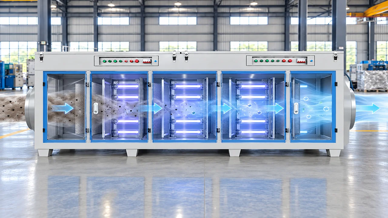
Contaminated process air enters through the inlet duct and is guided into the first internal treatment chamber.
The incoming gas stream is distributed across the treatment section so it can pass evenly through the UV reaction modules.
High-energy UV lamps irradiate the exhaust stream, breaking molecular bonds in odor compounds and VOCs and promoting further oxidation of the reaction products.
After photolysis and downstream treatment, the purified airflow is collected and discharged through the outlet duct.
Selected exhaust containing odor-causing gaseous compounds.
Compatible low- to moderate-concentration VOCs after composition and safety review.
Selected gaseous contaminants from compatible resin or polymer processing.
Selected odor and organic exhaust from compatible coating operations.
Selected odor streams after moisture and aerosol control.
Selected gaseous pollutants after source capture and pretreatment.
04 / Machine Architecture
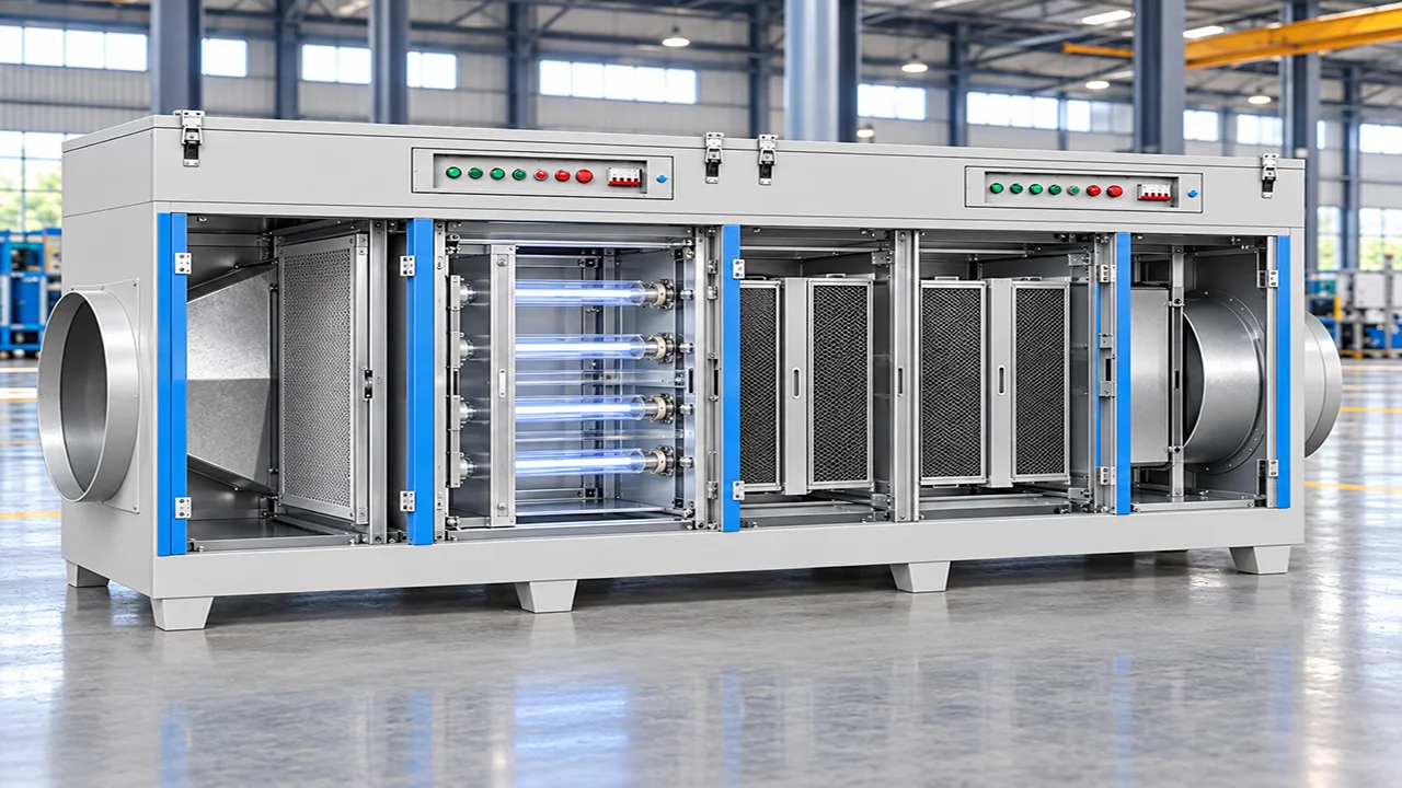
Receives contaminated exhaust and directs it into the internal purification chamber.
Spreads the incoming gas stream across the purifier cross-section before it reaches the treatment modules.
Provides the first treatment stage for intercepting larger particles and protecting the downstream UV section.
Houses the high-energy UV lamps that provide the primary photolysis treatment zone for gaseous pollutants.
Provide the downstream reaction surface used to support oxidation of intermediate compounds after UV irradiation.
Collects the treated airflow after the purification stages and guides it toward the discharge duct.
Provide operating controls, status indication and electrical protection for the UV treatment system.
Provide maintenance access to the internal modules and structural support for stable installation.
High-energy UV radiation initiates photochemical reactions: molecular excitation, bond cleavage and formation of reactive oxygen-containing species, without bulk thermal combustion of the exhaust stream.
Source-stated values retained for engineering documentation. Final specifications depend on the selected configuration, feed material and agreed operating conditions. Specification inputs listed on the published page: Lamp type, wavelength, intensity and quantity; Airflow, pressure drop and fan duty; Installed power and residence time; Inlet concentration range, temperature and humidity limits; Ozone or by-product control; Removal efficiency, outlet emissions and explosion rating; Dimensions, maintenance clearances and service life
Selected odor-causing gaseous compounds after composition assessment.
Low- or moderate-concentration streams subject to engineering review.
Compatible process gases after review.
After source capture and pretreatment.
No. Some compatible contaminants may be transformed toward simpler products, but complete mineralization, by-products and outlet results depend on the gas chemistry and reaction conditions and require validation.
Significant dust, oil mist, droplets and condensable aerosol should normally be removed upstream because they can foul lamps and interfere with UV exposure.
No. UV photolysis uses UV radiation and photochemical reactions; plasma uses an electrically generated plasma field; activated carbon adsorbs compatible molecules. They can be combined in a complete treatment system.
No universal ozone-control performance is stated. Possible ozone and other by-products must be assessed and controlled for the selected configuration and local requirements.
Provide gas flow, temperature, humidity, composition, contaminant concentrations, particulate/mist loading, target outlet limits, operating hours, installation country and available layout.
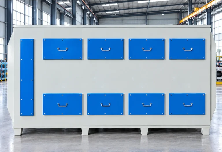
The Activated Carbon Adsorption System is an industrial exhaust-gas treatment unit designed to remove selected volatile organic compounds (VOCs) and odorous pollutants from process…
View Equipment →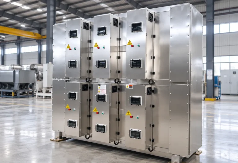
The Industrial Oil Fume Purification Equipment is designed to treat oil mist, fine aerosol, smoke and selected suspended particulate generated by industrial thermal and…
View Equipment →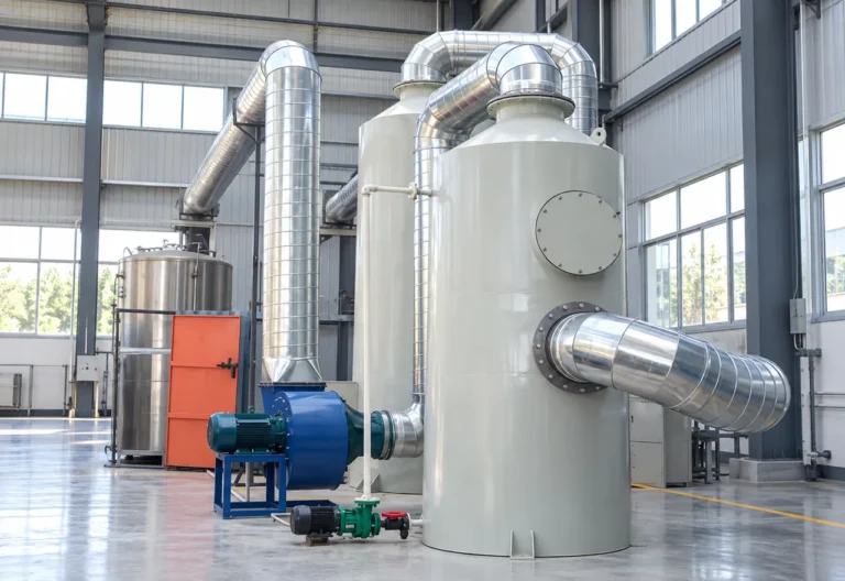
The BREM Water Spray Scrubber is a wet exhaust-treatment system designed to remove suitable particulate matter, soluble gaseous contaminants and selected acid or alkaline…
View Equipment →Send material, capacity, target output and site information for an application review.
You can also upload material photos, equipment images, plant layouts or technical documents.
You don't need to know all the technical details. Tell us what you're working with and what you want to achieve, and our team will help you determine the next step.