
01
Material Feeding
Mixed granular material enters through the upper inlet and falls onto the internal feed section.
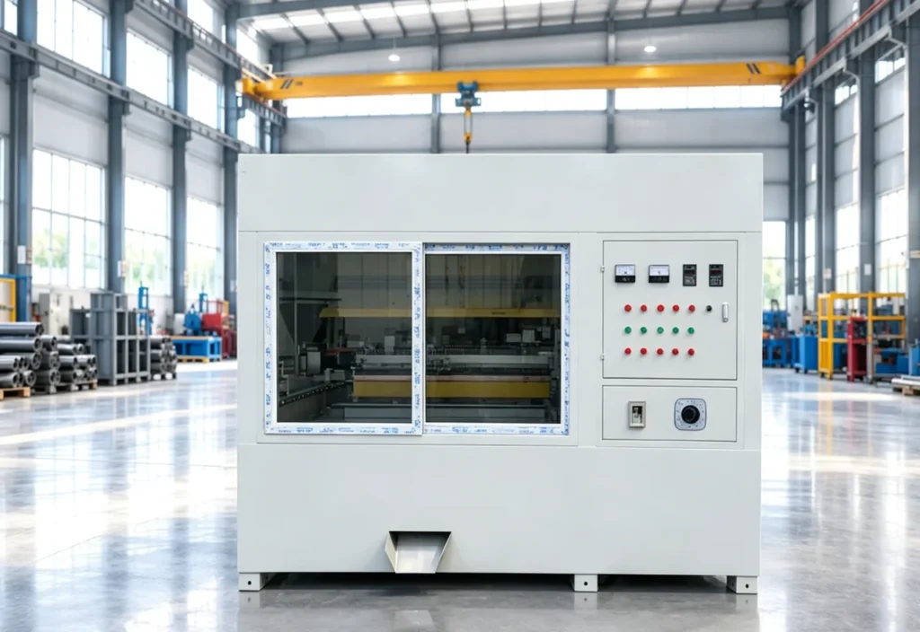
The Electrostatic Separator is a dry high-voltage separation machine for dividing conductive and non-conductive particles according to their different electrical behavior in an electrostatic field. It is used as a downstream upgrading stage for prepared copper/plastic, aluminum/plastic, PCB and selected mixed-plastic fractions.
A downstream finishing stage for prepared conductive/non-conductive particles, not a machine for whole PCBs, cables or batteries.
The Electrostatic Separator is a dry high-voltage separation machine for dividing conductive and non-conductive particles according to their different electrical behavior in an electrostatic field. It is used as a downstream upgrading stage for prepared copper/plastic, aluminum/plastic, PCB and selected mixed-plastic fractions. The separator is intended for controlled, free-flowing particles rather than whole or bulky scrap. Stable feed size, low moisture and suitable upstream liberation are important for consistent trajectories and product quality.
Source lists preliminary reference values only. They are not universal guarantees and require confirmation in the approved technical proposal.
02 / Operating Principle
Mixed granular material enters through the upper feed inlet and is distributed across the internal conveying section. As the material passes through the electrostatic separation zone, conductive and non-conductive particles respond differently to the electric field, allowing the separated fractions to move toward their respective discharge paths.
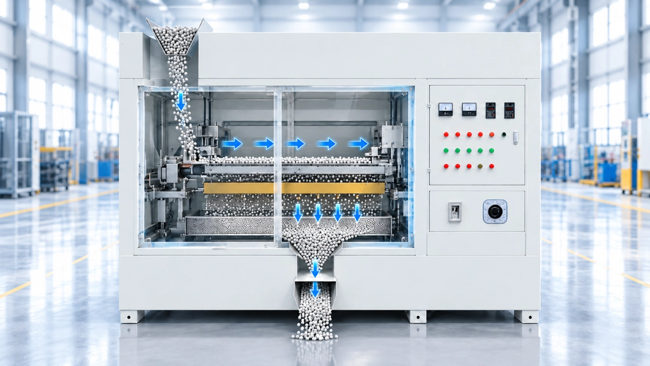
Mixed granular material enters through the upper inlet and falls onto the internal feed section.
The material is spread into a controlled layer and conveyed horizontally toward the electrostatic treatment zone.
Conductive and non-conductive particles follow different trajectories under the applied electric field and separate into distinct fractions.
The separated material fractions move downward and leave through the lower collection and discharge outlet.
Suitability depends on composition, feed condition and the selected equipment configuration.
Suitability depends on composition, feed condition and the selected equipment configuration.
Suitability depends on composition, feed condition and the selected equipment configuration.
Suitability depends on composition, feed condition and the selected equipment configuration.
Suitability depends on composition, feed condition and the selected equipment configuration.
04 / Machine Architecture
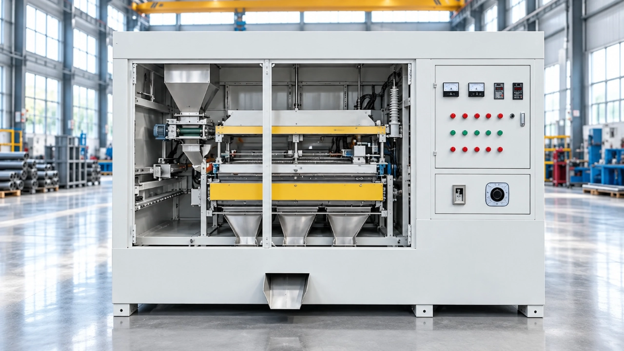
Meters and distributes prepared material onto the separation section at a controlled rate.
Establishes the electrostatic field used to create different particle trajectories in the separation zone.
Provides the grounded rotating surface where conductive and non-conductive particles follow different trajectories.
Drives the separation drum and controls rotational speed for stable material handling through the separation zone.
Direct separated conductive, non-conductive and intermediate fractions into their respective collection paths.
Removes particles retained on the drum surface at the designated release point.
Transfers intermediate material for collection or another separation pass when the configured process includes recirculation.
Houses the electrical controls and interlocks and provides the enclosed operating interface for the separator.
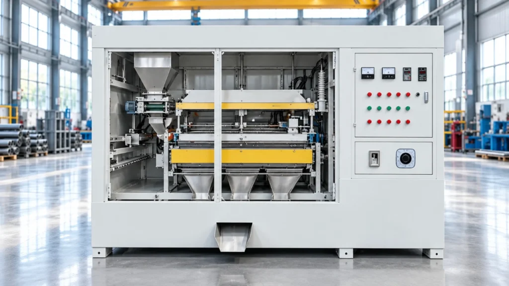
Conductive and non-conductive particles follow different trajectories in a high-voltage field on a grounded rotating drum. Three-stream collection keeps middlings out of saleable product.
| Parameter | Specification |
|---|---|
| Capacity | 1–10 t/day, depending on material and configuration |
| Overall size | approximately 1.7 × 1.5 × 2.5 m |
| Electrical supply | 220 V control power and 380 V main power |
These values are reference data from the cited source, not universal guarantees. Confirm model, throughput basis, feed size, moisture limit, installed power, high-voltage settings, collection layout and separation performance in the approved technical proposal.
Dry conductive/non-conductive upgrading after size reduction.
Downstream finishing where particles are liberated and dry.
Not for whole PCBs; only prepared particles after crushing/screening.
Conductive/non-conductive split after sample testing.
The feed should be liberated, dry and within a relatively controlled particle-size range. The acceptable range must be determined by sample testing because it depends on the selected drum, electrode and feed system.
No direct assumption should be made. Whole or bulky items require upstream dismantling, shredding and screening before electrostatic separation.
Purity and recovery depend on feed composition, liberation, moisture, particle size, voltage, drum speed, splitter position and recirculation. They should be established from representative test results rather than treated as fixed catalogue values.
It can be included as a conveyor or return elevator when required by the process design. Confirm the layout and control method in the quotation.
Provide material photos or samples, composition, particle-size distribution, moisture, required capacity, target products, desired purity/recovery, installation country, site power and available layout.
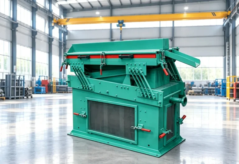
The Air Gravity Separator is a dry physical separation unit for classifying prepared granular material according to density, particle size and aerodynamic behavior.
View Equipment →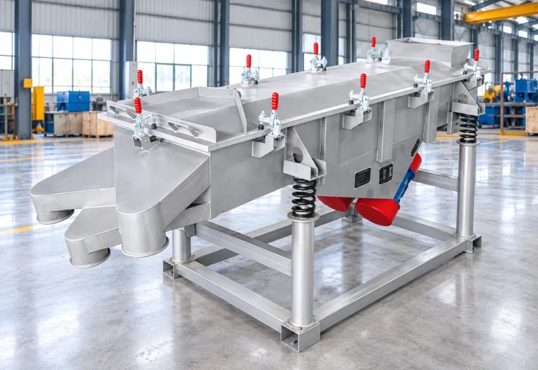
The Vibratory Separator is a linear screening machine designed to classify granular and powdered recycling materials into different particle-size fractions.
View Equipment →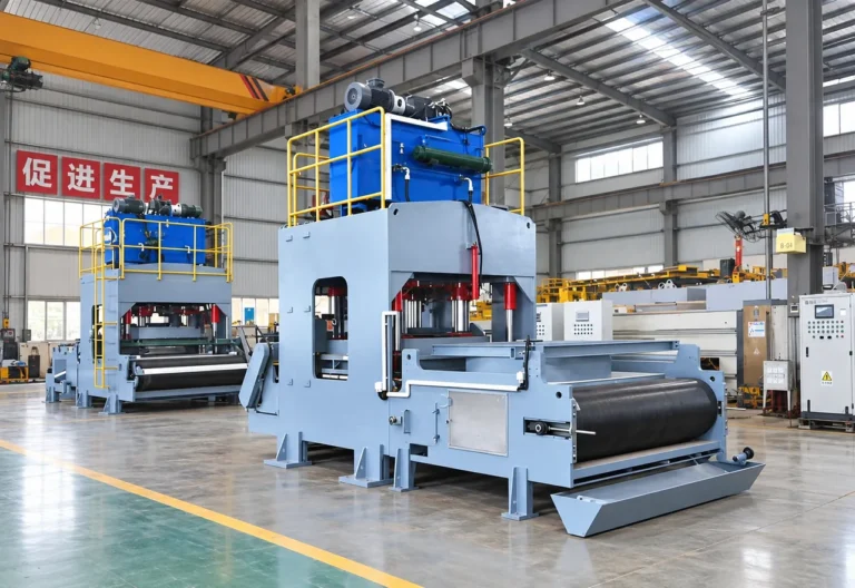
The Hydraulic Dewatering Machine is a high-pressure solid-liquid separation system for sludge, slurry and other high-moisture industrial materials.
View Equipment →Send material, capacity, target output and site information for an application review.
You can also upload material photos, equipment images, plant layouts or technical documents.
You don't need to know all the technical details. Tell us what you're working with and what you want to achieve, and our team will help you determine the next step.