Feed Preparation
High-moisture material enters the dewatering process. Depending on feed condition, an optional screw press, plate-and-frame filter press or belt filter press may be used to remove readily separable liquid before hydraulic pressing.
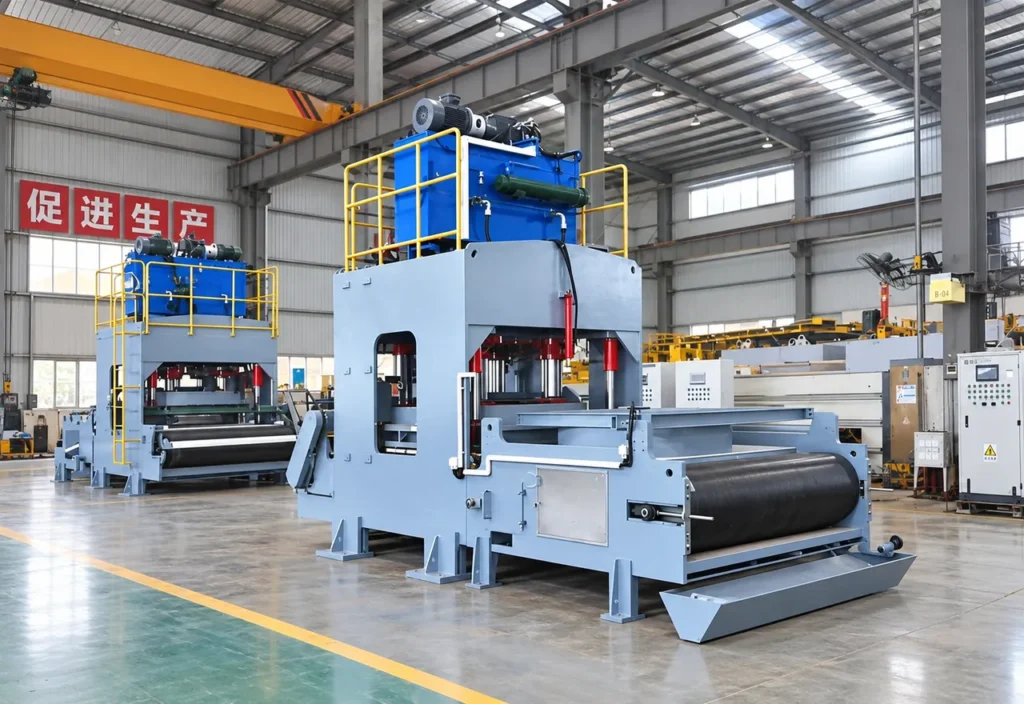
The Hydraulic Dewatering Machine is a high-pressure solid-liquid separation system for sludge, slurry and other high-moisture industrial materials. It uses hydraulic compression, a customized forming chamber and controlled liquid-discharge channels to mechanically remove water from the feed.
Mechanical water removal after optional pretreatment and before transport, thermal drying, disposal or resource recovery.
The Hydraulic Dewatering Machine is a high-pressure solid-liquid separation system for sludge, slurry and other high-moisture industrial materials. It uses hydraulic compression, a customized forming chamber and controlled liquid-discharge channels to mechanically remove water from the feed. Depending on the selected configuration, vacuum assistance can be integrated to support liquid removal from applicable materials. Compared with thermal drying, hydraulic dewatering reduces water content through mechanical pressure rather than relying primarily on heat, making it suitable as a preprocessing or volume-reduction stage before downstream drying, disposal, transport or resource recovery. The collected source identifies the XM-500/5000 as a representative configuration.
content-manifest.json flags product-98 ambiguous final moisture. Source 15%-55% is application-dependent and is not treated as a guaranteed fact.
02 / Operating Principle
High-moisture material enters the dewatering process. Depending on feed condition, an optional screw press, plate-and-frame filter press or belt filter press may be used to remove readily separable liquid before hydraulic pressing.
Prepared material is transferred into a buffer hopper to stabilize the feed rate and decouple pretreatment fluctuations from the dewatering cycle.
A metering system controls the amount of material supplied to each pressing cycle. Stable loading helps avoid uneven pressure distribution and inconsistent cake formation.
The distribution mechanism spreads material into the forming chamber to support uniform loading across the pressing zone. Forming-chamber geometry is selected for the feed and required discharge format.
Suitability depends on composition, feed condition and the selected equipment configuration.
04 / Machine Architecture
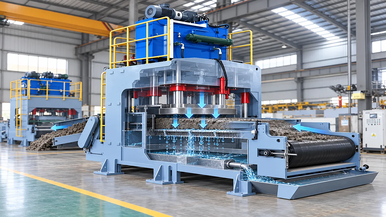
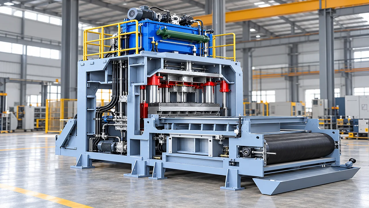
Supplies hydraulic pressure for the pressing system through the top-mounted motor, pump and oil tank assembly.
Provides protected access to the upper hydraulic assembly for inspection, maintenance and service work.
Delivers the main downward pressing force through the upper platen and hydraulic cylinder structure.
Maintain platen alignment and support the heavy press loads during the dewatering cycle.
Forms the main compression zone where wet material is compacted and liquid is forced out of the material layer.
Carries wet material into the machine and presents it to the pressing zone for continuous operation.
Collects separated liquid beneath the pressing area and directs it to the drainage outlet for discharge.
Integrates the lower pump components, piping runs and structural base that support stable operation of the whole machine.
Adjustable hydraulic compression in a customized forming chamber expels liquid. Vacuum assistance is optional and only included when testing supports it.
| Parameter | Specification |
|---|---|
| Representative model | XM-500/5000 |
| Capacity | approximately 10-28 t/h, depending on material and moisture condition |
| Site footprint | approximately 60-200 m², depending on the complete layout |
| Hydraulic pressure | adjustable according to material and configuration |
| Final moisture | source references approx. 15%-55% for different applications; not a universal guarantee |
Capacity and footprint are source-stated ranges, not guarantees. Final moisture (source 15%-55%) is ambiguous and application-dependent. Confirm feed rate, solids concentration, incoming moisture, pressing pressure, cycle time, forming-chamber volume, drainage, vacuum duty, installed power and the moisture test method in the approved proposal.
Before transport or disposal.
Mechanical water removal ahead of a dryer.
Wet recycling residues after testing.
Coal slurry, mineral slurry and process sludge.
Where the material is compatible with the forming system.
No. Vacuum assistance is configuration-dependent and should be included only when material testing and the approved process design support it.
No. Throughput and final moisture vary by material, moisture, solids concentration, pretreatment and operating conditions. The final proposal must define the test method and acceptance basis.
Not always. Pretreatment is optional and selected according to feed rheology and the required process duty. A screw press, plate-and-frame press or belt press may be considered as an alternative upstream stage.
It may be possible after feed-specific testing and a review of sealing, liquid handling, fire risk, vapor control and local environmental requirements.
Provide representative samples, composition, incoming moisture, solids concentration, viscosity or flow behavior, required capacity, target moisture, installation country, site utilities and available layout.
Send material, capacity, target output and site information for an application review.
You can also upload material photos, equipment images, plant layouts or technical documents.
You don't need to know all the technical details. Tell us what you're working with and what you want to achieve, and our team will help you determine the next step.