
01
Fume Intake
Oil-laden exhaust enters through the inlet duct and is distributed into the first treatment chamber.
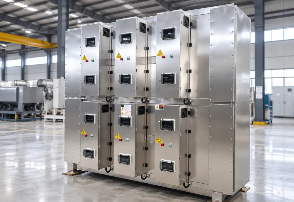
The Industrial Oil Fume Purification Equipment is designed to treat oil mist, fine aerosol, smoke and selected suspended particulate generated by industrial thermal and manufacturing processes. It combines mechanical pre-filtration, electrostatic ionization and electrostatic collection to progressively remove larger droplets and fine charged aerosol particles from the exhaust stream.
Installed after local exhaust collection and before a fan or stack. Not an activated-carbon VOC purifier.
The Industrial Oil Fume Purification Equipment is designed to treat oil mist, fine aerosol, smoke and selected suspended particulate generated by industrial thermal and manufacturing processes. It combines mechanical pre-filtration, electrostatic ionization and electrostatic collection to progressively remove larger droplets and fine charged aerosol particles from the exhaust stream. Unlike a simple coarse filter, the electrostatic stage charges fine oil-mist particles and captures them on collecting electrodes. The collected liquid can coalesce and drain into the collection section. The equipment is normally integrated with exhaust ducting, an induced-draft fan and other environmental-control equipment according to the actual exhaust stream. This product is primarily for oil droplets, oil aerosol and smoke. It should not be presented as a general VOC adsorption system; gas-phase VOC treatment may require activated carbon, thermal, catalytic, plasma or other specialist equipment.
The collected source references capture of larger droplets above approximately 5 micrometers. That value is source-stated and is not treated as a guaranteed cut point.
02 / Operating Principle
Oil-laden exhaust enters the purification cabinet through the inlet duct and passes through a sequence of internal treatment stages. Droplets and particulate contaminants are progressively captured by the pre-separation and filtration sections, while the cleaned airflow is guided through the final treatment stage and discharged through the outlet.
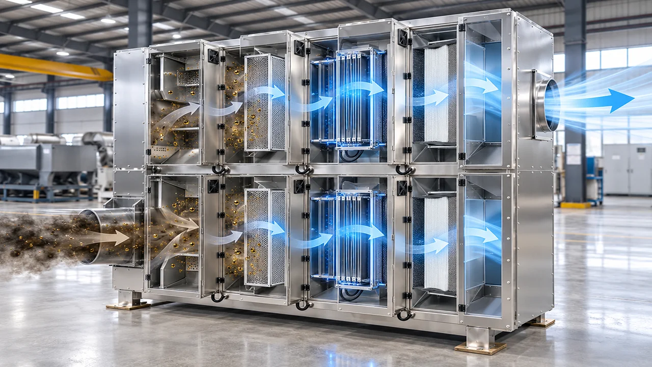
Oil-laden exhaust enters through the inlet duct and is distributed into the first treatment chamber.
The incoming gas stream passes through the first separation section, where larger oil droplets and coarse contaminants are removed from the airflow.
The partially cleaned airflow continues through the central purification modules, where finer oil mist and suspended particles are captured.
After final filtration, the treated air is collected in the outlet section and discharged through the clean-air duct.
Fine oil droplets from machining, heat treatment and lubrication processes.
Smoke and aerosol from heating, quenching and thermal forming.
Oil-containing exhaust from forging, rolling or metal-processing operations.
Fine liquid or particulate aerosol from selected coating, impregnation and manufacturing operations.
Selected smoke streams that can be treated by mechanical and electrostatic collection after engineering review.
04 / Machine Architecture
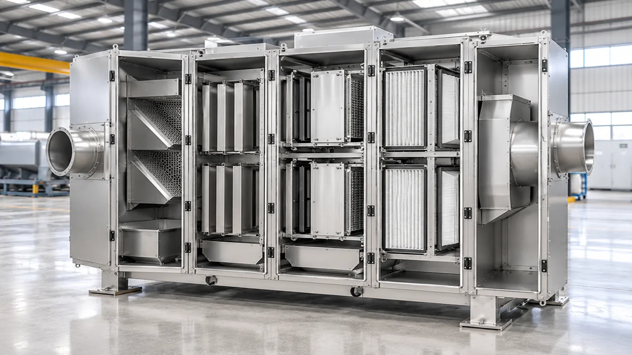
Receives oil-laden exhaust and directs it into the first internal treatment chamber.
Spreads the incoming gas stream across the purifier cross-section before it reaches the treatment modules.
Provides the first-stage capture zone for larger oil droplets and coarse contaminants in the exhaust stream.
Forms the central high-voltage treatment section used to capture finer oil mist and suspended particles.
Provides downstream polishing filtration to capture remaining fine droplets and particulate matter.
Collects the treated airflow after the final purification stage and guides it toward the discharge side.
Provide access to internal purification modules for inspection, cleaning and replacement.
Encloses and supports the multi-stage purification modules within a rigid industrial housing.
Three-stage purification: inertial / mechanical pre-filtration, ionization, and electrostatic precipitation. Optional after-filter may follow.
Source-stated values retained for engineering documentation. Final specifications depend on the selected configuration, feed material and agreed operating conditions. Specification inputs listed on the published page: Exhaust flow, temperature and operating schedule; Oil-mist loading, droplet-size distribution and particulate content; Gas chemistry, corrosivity and flammability risk; Required outlet limit and test method; Pre-filter, ionizer, collector and after-filter arrangement; High-voltage duty, fan duty and pressure-drop allowance; Drain, inspection, cleaning and waste-handling method; Housing material, dimensions, service clearance and local compliance
Fine oil droplets after source capture.
Thermal oil smoke and quenching oil mist.
Forging, rolling or metal-processing oil-containing exhaust.
Only after contaminant, temperature, particulate load and fire-risk review.
No. It is primarily an oil-mist, aerosol and smoke collection system. Gas-phase VOC treatment may require a separate activated-carbon or other specialist stage.
No. The approximately 5 micrometer reference applies to the source description and is not a universal guaranteed cut point. Confirm performance through model-specific testing.
There is no universal interval. Cleaning should be based on oil loading, pressure drop, outlet monitoring and the approved maintenance plan.
It may be suitable for selected smoke streams after source capture and contaminant review. The actual gas chemistry, temperature, particulate load and fire risk must be determined first.
Provide exhaust flow, temperature, oil and particulate loading, contaminant chemistry, target outlet limits, operating hours, installation country, available layout and fire/safety requirements.
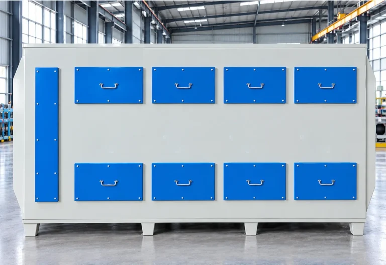
The Activated Carbon Adsorption System is an industrial exhaust-gas treatment unit designed to remove selected volatile organic compounds (VOCs) and odorous pollutants from process…
View Equipment →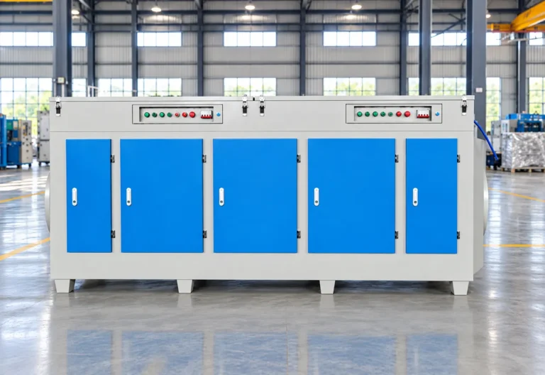
UV Photolysis Purification Equipment is designed for selected industrial exhaust streams containing odor compounds and gaseous organic contaminants.
View Equipment →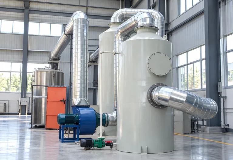
The BREM Water Spray Scrubber is a wet exhaust-treatment system designed to remove suitable particulate matter, soluble gaseous contaminants and selected acid or alkaline…
View Equipment →Send material, capacity, target output and site information for an application review.
You can also upload material photos, equipment images, plant layouts or technical documents.
You don't need to know all the technical details. Tell us what you're working with and what you want to achieve, and our team will help you determine the next step.