Skip to content
Battery Recycling Equipment Manufacturing Engineering · Manufacturing · Global Service
PCB Pre-Treatment & Component Recovery

PCB Component Dismantling & Recycling Line

An automated pre-treatment system for removing mounted electronic components from waste printed circuit boards before downstream board crushing and material separation. Controlled heating softens solder, while rotating mechanical action releases components from the PCB substrate. The system separates dismantled electronic components from the remaining PCB board and integrates fume capture, wet scrubbing, adsorption and project-specific exhaust purification for the heating process. Final heating temperature, throughput and exhaust-treatment configuration are confirmed according to board type, solder composition, component loading and local environmental requirements.

01 / Production line overview

Remove Electronic Components Before PCB Crushing

PCB component dismantling / de-soldering pre-treatment — not the same as PCB crushing and electrostatic separation.

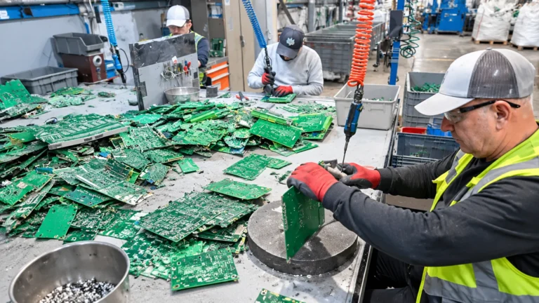
Waste printed circuit boards contain a wide variety of mounted components, metals and materials. Instead of sending fully populated boards directly into a crushing line, the dismantling system first separates the mounted electronic components from the PCB substrate so that each stream can enter a more appropriate downstream recovery route.

The system uses controlled heating to soften or melt solder joints, followed by drum rotation and mechanical friction to release mounted components from the board. As the machine operates, electronic components detach from the PCB substrate and are discharged separately from the stripped board.

The dismantled PCB substrate can then be sent to downstream crushing, pulverizing and metal/non-metal separation equipment. The recovered electronic components can be classified separately according to component type, material value and hazardous-material handling requirements.

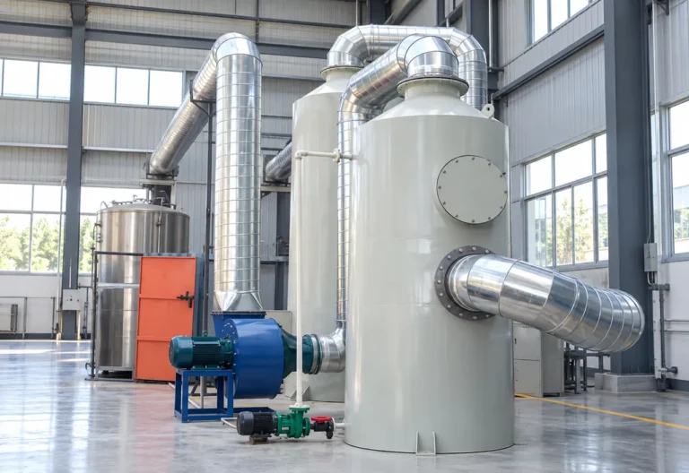
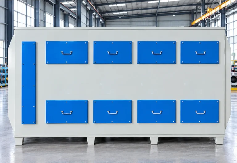
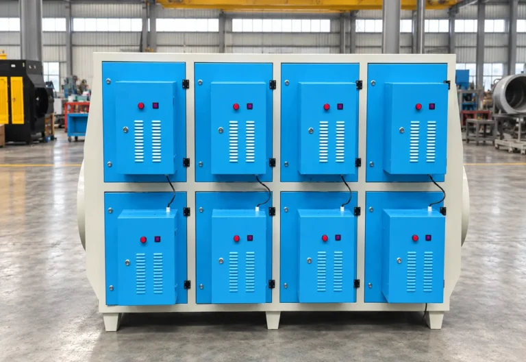
Because heating can generate solder fumes, resin vapors, odor and fine particulate, the dismantling line is integrated with an exhaust collection and purification system. The supplied source configuration includes a fume hood, water spray tower, activated-carbon adsorption, plasma purification and an induced-draft fan.

01 — Automated Component Removal: Controlled heating and rotating mechanical action replace much of the manual work required to remove components from waste PCBs.
02 — Separate Output Streams: Electronic components and stripped PCB substrates are discharged separately for different downstream recovery routes.
03 — Downstream PCB Preparation: Removing mounted components simplifies subsequent board crushing and metal/non-metal separation.
04 — Integrated Fume Treatment: Heating exhaust is collected and treated through a multi-stage purification train configured for the project.

This page describes PCB electronic-component dismantling / de-soldering before downstream board crushing. It is not a copper-clad laminate pulverizing line, complete e-waste appliance dismantling line, precious-metal refining line or hydrometallurgical extraction process.

Remove Electronic Components Before PCB Crushing
02 / Feedstock & Outputs

Populated Waste PCBs In, Components and Stripped Boards Out

The dismantling system is intended for populated circuit boards that require electronic-component removal before downstream material recovery. Feed composition and board construction determine the required heating, residence time and exhaust-treatment settings.

Feedstock

Populated Waste PCBs

Populated Waste PCBs

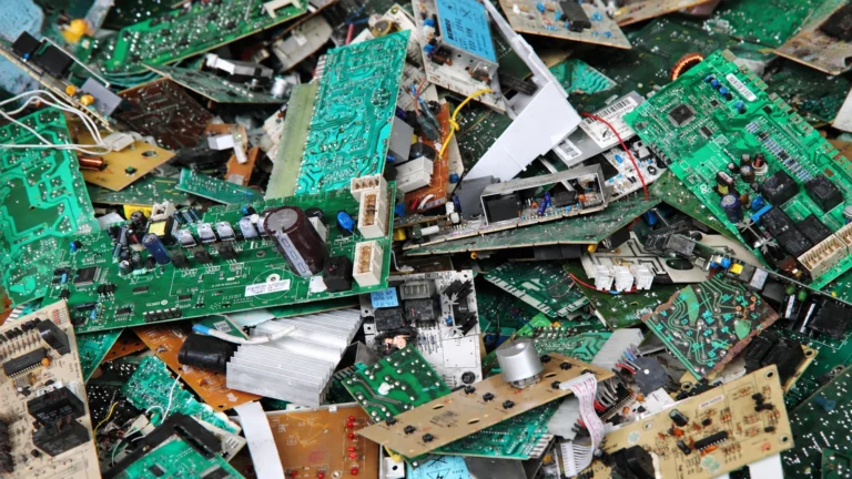
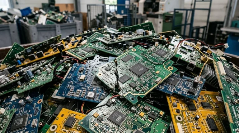
End-of-life printed circuit boards carrying mounted electronic components and soldered connections. Typical forms: computer boards; control boards; television / appliance boards; communication boards; mixed prepared PCB assemblies.

PCB Production / Assembly Rejects

PCB Production / Assembly Rejects

Rejected or obsolete assembled circuit boards that still contain mounted components and can benefit from de-soldering before downstream processing.

Prepared Electronic Boards

Prepared Electronic Boards

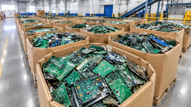
Boards that have already been removed from housings, batteries, large heat sinks or other incompatible assemblies and are suitable for controlled dismantling.

Outputs

Dismantled Electronic Components

Dismantled Electronic Components

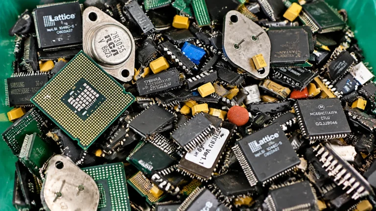
Components released from the PCB by controlled de-soldering and mechanical rotation. These components can be classified separately for reuse, metal recovery or hazardous-material handling.

Stripped PCB Substrate

Stripped PCB Substrate

PCB boards after mounted components have been removed. These stripped boards are easier to process in downstream crushing, pulverizing and metal/non-metal separation systems.

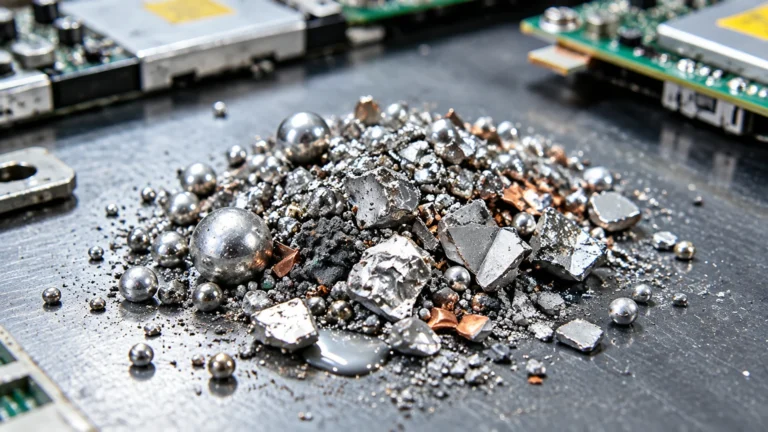
Recovered Solder / Metal Residue

Recovered Solder / Metal Residue

Solder and fine metal-bearing residue generated during heating and component release may be collected separately depending on the current equipment design and operating method.

Captured Fume / Dust Residue

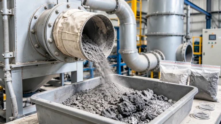
Captured Fume / Dust Residue

Particulate and adsorbed contaminants recovered from the exhaust-treatment system and managed according to their composition and local environmental requirements.

Whole appliances, batteries, large transformers, pressurized parts, mercury-containing devices and other incompatible components should be removed before the boards enter the dismantling machine. Feedstock should be reviewed for hazardous components and local handling requirements.

03 / Complete Production Line & Process Overview

Controlled De-Soldering, Mechanical Dismantling and Fume Purification

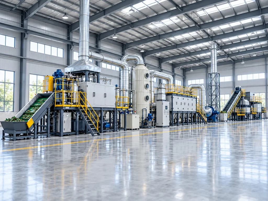
The line combines PCB heating and mechanical component removal with a dedicated exhaust-treatment train. The dismantling stage and the air-treatment stage operate as one coordinated system.

Process Stages

Controlled heating softens solder; drum friction releases components; stripped boards and components discharge separately while fumes enter a multi-stage purification train.

01

PCB Inspection & Preparation

Incoming boards are checked for batteries, large heat sinks, oversized parts, hazardous components and incompatible attachments before entering the dismantling machine.

02

Controlled Feeding

Prepared populated PCBs are fed into the dismantling machine at a controlled rate so that board residence time and heating conditions remain stable.

03

Controlled Heating / De-Soldering

Electric or gas-assisted heating raises the process temperature until the solder joints soften sufficiently for component release. The exact operating temperature must follow the current engineering configuration and solder type.

04

Rotary Mechanical Dismantling

The PCB rotates and contacts the internal drum structure, creating controlled friction and agitation. As solder joints soften, mounted electronic components detach from the board.

05

Electronic Component Discharge

Released electronic components are separated from the PCB stream and discharged for downstream classification, reuse or material recovery.

06

Stripped PCB Discharge

The remaining PCB substrate is discharged separately and can be transferred to a downstream PCB crushing and separation line.

07

Fume Capture

A dedicated fume hood and negative-pressure exhaust system capture smoke, odor, vapor and fine particulate generated during heating and de-soldering.

08

Water Spray Scrubbing

Captured exhaust enters a water spray tower where particulate and suitable contaminants are removed or reduced through gas-liquid contact.

09

Adsorption & Purification

The source configuration routes the scrubbed exhaust through activated-carbon adsorption and plasma purification for additional odor / contaminant treatment. Final treatment stages must be selected according to the actual exhaust composition and local regulations.

10

Induced Draft & Exhaust Discharge

An induced-draft fan maintains system airflow and sends treated exhaust to the approved discharge point after the configured purification stages.

The supplied process diagrams show PCB dismantling as the pre-treatment stage, with stripped boards moving to downstream crushing/separation and electronic components moving to separate recycling. Exhaust treatment is shown as a dedicated parallel system rather than part of the material-discharge path.

04 / Main Equipment Configuration

Core Equipment for PCB Dismantling and Exhaust Treatment

The main equipment combines automated component dismantling with a multi-stage exhaust-treatment system. Only published BREM Product posts are linked below; the core dismantling machine is described as a line component until a dedicated Product CPT exists.

Wet Scrubbing

Core process machine without a matching published Product CPT (not auto-created): PCB dismantling / de-soldering machine — controlled heating, drum rotation and component detachment (source reference model 400 / 1.5 + 0.37 kW). Supporting line components without standalone Product CPT: fume hood (model 400), induced-draft fan (model 400 / 3 kW), collection ducting, exhaust pipework, compliant air outlet and electrical control system.

05 / Technical Parameters

Reference Dismantling and Exhaust-Treatment Configuration

The supplied material provides a reference equipment configuration and a source-reported throughput range. Values below are reference data and must be confirmed by BREM engineering before quotation or contract commitment.

Parameter Specification
Processing Capacity Reference throughput: 200–500 kg/h — not guaranteed continuous output for all PCB types
Applicable Feedstock Prepared populated waste PCBs / assembled boards after incompatible parts are removed
Applicable Battery Chemistry Soldered PCB assemblies with mixed electronic components (project-reviewed)
Processing Method Controlled heat + rotating mechanical friction / agitation; multi-stage fume treatment
Recovered Fractions Dismantled electronic components + stripped PCB substrate (+ optional solder/fine metal residue)
Automation Level Automated / coordinated electrical control
Installed Power Reference source models include dismantler 1.5+0.37 kW, spray 2.2 kW, plasma 1.2 kW, ID fan 3 kW — project total confirmed by engineering
Typical Floor Space Configured by project
Operating Mode Continuous / semi-continuous PCB de-soldering with dedicated exhaust train
Dust Control Fume hood / source capture + negative-pressure extraction
Exhaust Treatment Fume capture → water spray → activated carbon → project-specific plasma/polishing → induced draft
Utilities Electric or gas-assisted heating according to project configuration; power, water for scrubber and utilities confirmed before final design

REFERENCE CONFIGURATION FROM SUPPLIED MATERIAL (not universal guaranteed performance):

• PCB dismantling machine — model 400 — 1.5 + 0.37 kW — 1 set
• Fume hood — model 400 — 1 set
• Water spray tower — model 1200 — 2.2 kW — 1 set
• Activated-carbon adsorption box — model 1800 — 1 set
• Plasma purification unit — model 1200 — 1.2 kW — 1 set
• Induced-draft fan — model 400 — 3 kW — 1 set
• Reference throughput: 200–500 kg/h
• Staffing reference: generally 2 operators/shift (source phrasing); actual staffing is project-dependent

HEATING TEMPERATURE — SOURCE REFERENCE DISCREPANCY:
Controlled heating softens the solder so components can be mechanically released from the PCB substrate. The final operating temperature is confirmed according to solder type, board construction and the current equipment configuration. The supplied source material references approximately 120–150°C in different descriptions (approximately 120°C in one section; approximately 150°C in another). Current engineering data should be used for the final operating setpoint. Do not treat either value alone as a confirmed universal specification.

All model numbers, throughput, staffing and temperature references above are derived from the supplied technical material. Current project specifications must be confirmed by BREM engineering before quotation or contract commitment.

06 / Output Quality

Separated Components and Cleaner PCB Feed for Downstream Recycling

The dismantling process is designed to preserve two distinct material streams: removed electronic components and the stripped PCB substrate. This separation reduces unnecessary mixing before downstream recovery.

Dismantled Electronic Components

Recovered mounted components that have been released from the PCB substrate during controlled de-soldering. Components can be further classified by type, material value or hazardous-material handling requirement.

Composition
Not inventing removal % — confirm by current testing if required
Downstream Use
Reuse, resale, base/precious-metal recovery or hazardous-material handling by component type.

Stripped PCB Substrate

PCB board material after component removal, prepared for downstream crushing, pulverizing and metal/non-metal separation.

Particle Size
Board-form substrate
Downstream Use
Downstream PCB crushing / pulverizing / metal–non-metal separation line.

Solder / Fine Metal Residue

Solder and fine metal-bearing material generated during de-soldering may be collected as a separate secondary stream depending on machine configuration and discharge design.

Downstream Use
Collected when the current equipment design supports separate discharge.

Captured Exhaust Residue

Particulate and adsorbed contaminants captured by the scrubbing and adsorption system and handled according to their verified composition and environmental requirements.

Downstream Use
Managed per verified composition and local environmental requirements.

The supplied material does not provide verified component-removal percentage, solder-recovery rate or bare-board cleanliness specification. These figures are not invented. Add only after engineering verification of current test data.

07 / Safety Engineering

Safety Controls for Heating, Rotating Equipment and PCB Fumes

PCB dismantling combines controlled heating, rotating mechanical equipment and exhaust handling. The line therefore requires coordinated thermal, mechanical and ventilation safeguards.

01

Controlled Feed Inspection

Remove batteries, pressurized devices, oversized metal parts and other incompatible components before PCB boards enter the dismantling machine.

02

Temperature Control

Automatic temperature control maintains the selected heating range and should include over-temperature alarms and shutdown logic appropriate to the current machine design.

03

Rotating Equipment Guarding

Access doors, rotating drum sections and drive components require guards and interlocks to prevent access during operation.

04

Negative-Pressure Fume Capture

The dismantling chamber and fume hood should operate under controlled extraction so heating fumes do not escape uncontrolled into the workshop.

05

Fire / Thermal Risk Review

PCB resin, residual polymers and component materials can respond differently to heat. Final operating temperature and fire-protection measures must be selected according to the actual feedstock and current process design.

06

PLC Interlocks & Emergency Stops

Heating, drum rotation, exhaust fan and purification equipment should be interlocked so that the system does not heat or operate without the required ventilation and fault protection.

Do not describe the machine as universally safe for all assembled boards. Feedstock must be reviewed for batteries, combustible components, hazardous substances and unusual assemblies before processing.

08 / Environmental Control

Multi-Stage Fume and Odor Treatment

Heating populated PCBs can release solder fumes, resin vapors, odor and fine particulate. The source configuration combines source capture with wet scrubbing, activated-carbon adsorption and an additional purification stage before induced-draft exhaust.

A

Fume Hood & Source Capture

A collection hood above the dismantling machine captures smoke, odor and fine particulate directly at the point of generation.

B

Water Spray Scrubbing

The captured exhaust passes through a spray tower for gas-liquid contact and removal of suitable particulate and contaminants.

C

Activated Carbon Adsorption

After scrubbing, activated-carbon adsorption treats odor and suitable gaseous contaminants before further polishing or discharge.

D

Plasma / Project-Specific Polishing

The supplied source includes a plasma purification unit before the induced-draft fan. The final polishing technology should be selected according to actual exhaust composition, local regulations and current BREM environmental-engineering practice.

Unsupported absolute emission claims from legacy marketing copy are not used on this page. Exhaust performance is project-specific and must meet applicable local requirements after engineering confirmation.

09 / Real Project Case

PCB Dismantling Reference Configuration

Reference Configuration / Process Equipment Material — not a named customer case.

Reference Configuration

The reference process heats populated PCBs under controlled conditions, then uses drum rotation and mechanical friction to release mounted electronic components from the substrate. Components and stripped boards discharge as separate streams for different downstream routes. The supplied exhaust-treatment configuration includes a fume hood, water spray tower, activated-carbon adsorption box, plasma purification unit and induced-draft fan. The source lists a reference dismantling capacity of 200–500 kg/h. Heating temperature in the source material is not a single fixed figure: different sections reference approximately 120°C and approximately 150°C. Final setpoint must follow current engineering data.

Feedstock
Prepared populated waste PCBs
Main Objective
Separate electronic components from PCB substrate before board crushing
Reference Throughput
200–500 kg/h
Core Process
Controlled heating + rotary mechanical dismantling
Exhaust Treatment
Fume hood → water spray → activated carbon → plasma → ID fan

No customer name, country, commissioning year, annual output or ROI is invented. Label remains Reference Configuration unless verified customer-case data is available.

10 / FAQ

PCB Dismantling Line FAQ

Resolve dismantling-route, temperature-reference and exhaust-treatment questions before requesting a proposal.

What does the PCB dismantling machine do?

It heats populated waste circuit boards so that solder joints soften, then uses rotating mechanical action to release electronic components from the PCB substrate. The components and stripped boards are collected as separate material streams.

Why dismantle components before crushing the PCB?

Different electronic components can contain different metals and materials. Removing them before board crushing reduces unnecessary mixing, allows components to be classified separately and prepares a cleaner PCB substrate for downstream crushing and metal/non-metal separation.

What operating temperature does the machine use?

The supplied technical material contains two reference values: approximately 120°C in one section and approximately 150°C in another. The final operating temperature should therefore be confirmed from the current BREM machine specification and adjusted according to solder type, board construction and process requirements.

What happens to the stripped PCB board after dismantling?

The stripped board can be transferred to a downstream PCB recycling line for crushing, pulverizing and separation of metal-rich and non-metal fractions.

What happens to the removed electronic components?

The components can be classified separately for reuse, resale, precious/base-metal recovery or hazardous-material handling depending on component type and local recycling requirements. The dismantling machine itself does not perform final precious-metal refining.

How are heating fumes treated?

The supplied configuration captures fumes at the dismantling machine and routes them through water spray scrubbing, activated-carbon adsorption, an additional purification stage and induced-draft exhaust. The final treatment train should be selected according to actual exhaust composition and local regulations.

What processing capacity is available?

The supplied source reports a reference throughput of approximately 200–500 kg/h. Actual throughput depends on board size, component density, solder type, residence time, heating conditions and the required dismantling quality.

What information is required for a technical proposal?

Please provide PCB photos or samples, board dimensions, component density, board type, expected hourly or daily throughput, solder / assembly information if known, desired dismantling quality, downstream recycling plan, project location, available plant space, power standard and local exhaust requirements.

11 / Request a Technical Proposal

Send Your PCB Samples and Dismantling Requirements

Provide BREM with your populated PCB material, target capacity and downstream recycling plan. Our engineering team will review the boards and recommend the dismantling, heating, fume-treatment and discharge configuration for your project. Include board photos or samples, dimensions, component density, capacity target, plant space, power standard and local exhaust requirements.

You can also upload material photos, equipment images, plant layouts or technical documents.