
01
Contaminated Air Inlet
Contaminated air enters the system through the inlet duct and moves into the internal distribution chamber.
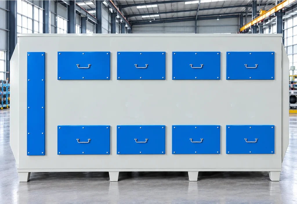
The Activated Carbon Adsorption System is an industrial exhaust-gas treatment unit designed to remove selected volatile organic compounds (VOCs) and odorous pollutants from process air. It uses porous activated carbon as the adsorbent. The carbon's developed internal surface provides adsorption sites where compatible gas-phase contaminants can be retained before treated air is discharged or sent to a downstream treatment stage.
Typically installed as a polishing stage after gas collection and any required dust, mist or scrubber pretreatment.
The Activated Carbon Adsorption System is an industrial exhaust-gas treatment unit designed to remove selected volatile organic compounds (VOCs) and odorous pollutants from process air. It uses porous activated carbon as the adsorbent. The carbon's developed internal surface provides adsorption sites where compatible gas-phase contaminants can be retained before treated air is discharged or sent to a downstream treatment stage. The equipment is typically installed as part of an exhaust collection and purification system rather than operated as an isolated machine. It is particularly suitable for low- to moderate-concentration VOC and odor streams that are compatible with activated-carbon adsorption.
The collected source does not provide reliable model-specific values for airflow, carbon loading, pressure drop or replacement interval. Carbon grade, pretreatment and safety controls must be selected for the actual contaminant mixture.
02 / Operating Principle
Contaminated process air enters the adsorption cabinet through the inlet duct and is distributed into multiple internal flow channels. As the air passes through the activated carbon beds, odor molecules and VOCs are adsorbed by the carbon media, and the treated air is collected and discharged through the outlet duct.
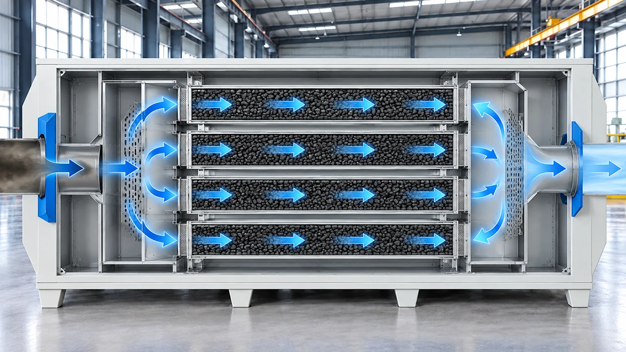
Contaminated air enters the system through the inlet duct and moves into the internal distribution chamber.
The plenum and perforated distribution section split the airflow evenly and guide it into the adsorption layers.
The gas stream passes through the activated carbon beds, where VOCs, odors and other gaseous pollutants are adsorbed by the carbon media.
After adsorption, the treated air is collected in the outlet chamber and discharged through the outlet duct for downstream exhaust or release.
Volatile organic compounds compatible with activated-carbon adsorption, subject to concentration, temperature, humidity and safety review.
Selected odor-containing gases from industrial processes, wastewater treatment and sludge handling.
Low- to moderate-concentration solvent vapors may be considered after engineering review and flammability assessment.
Selected odor streams containing compatible sulfur or amine compounds after suitable moisture and aerosol control.
Residual VOC or odor streams from suitable recycling operations after source capture and particulate pretreatment.
04 / Machine Architecture
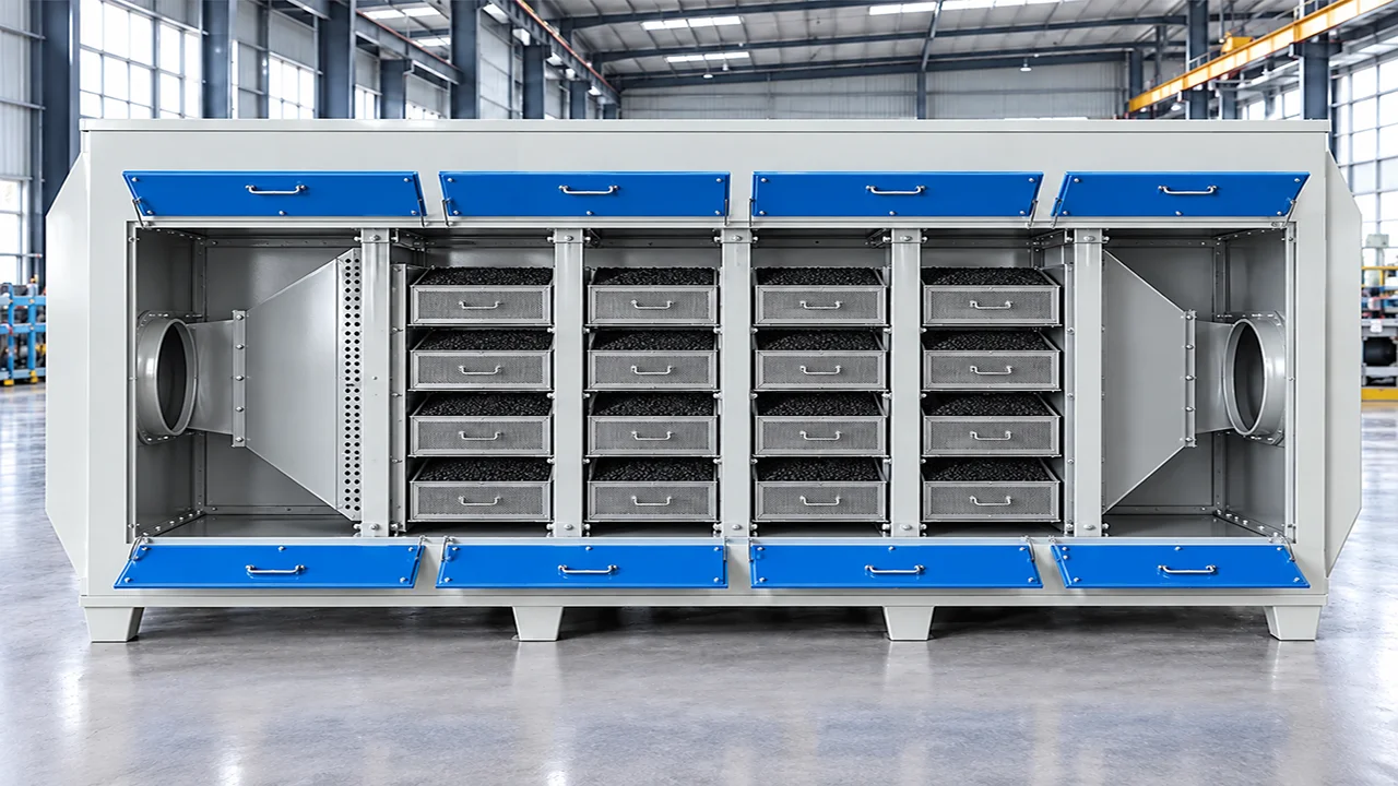
Receives contaminated process air and distributes it into the internal adsorption section for even flow across the carbon beds.
Provide service access to the upper carbon-loading positions for media inspection, replacement and maintenance.
Forms the main internal space where the air stream passes through the activated carbon media for pollutant adsorption.
Provide service access to the lower adsorption positions and support organized carbon-media replacement.
Encloses the adsorption beds and maintains the flow path through multiple carbon-loading compartments.
Collects the treated air after adsorption and guides it toward the outlet side of the cabinet.
Allow routine inspection, access to the internal chamber and removal of carbon modules during maintenance.
Supports the full adsorption cabinet and provides a rigid enclosed structure for stable industrial operation.
Porous activated carbon provides adsorption sites for compatible VOC and odor compounds. The unit is a mechanical adsorption-box stage, not a high-temperature oxidizer.
Source-stated values retained for engineering documentation. Final specifications depend on the selected configuration, feed material and agreed operating conditions. Specification inputs listed on the published page: Gas flow, temperature, humidity and operating schedule; Target contaminants and inlet concentration range; Required outlet limit and test method; Carbon type, bed arrangement and loading quantity; Pressure-drop allowance and fan duty; Upstream dust, mist or scrubber requirements; Access clearances, dimensions, materials and local compliance; Carbon monitoring, replacement, regeneration and disposal method
Used after source capture and primary particulate treatment for compatible residual VOC or odor.
Selected odor-containing gases from industrial processes after moisture and aerosol control.
Compatible sulfur or amine odor streams after suitable pretreatment.
Residual VOC or odor from suitable recycling operations. It does not replace process enclosure or specialist high-temperature treatment.
No. Adsorption compatibility and capacity vary by contaminant, concentration, humidity, temperature, carbon grade and competing compounds. A material-specific engineering review is required.
Significant dust, aerosols or oil mist should be removed upstream to protect the carbon bed and avoid rapid blockage or unsafe loading. The pretreatment sequence must be determined for the gas stream.
No universal interval is stated. Replacement should be based on outlet monitoring, loading, pressure drop, operating conditions and the approved maintenance plan.
It may serve as a downstream polishing stage for compatible residual VOC or odor after source capture and primary particulate treatment. The complete gas chemistry and safety assessment are required before selection.
Provide gas flow, temperature, humidity, contaminants, inlet concentrations, target outlet limits, operating hours, upstream treatment, installation country, available layout and carbon-handling requirements.
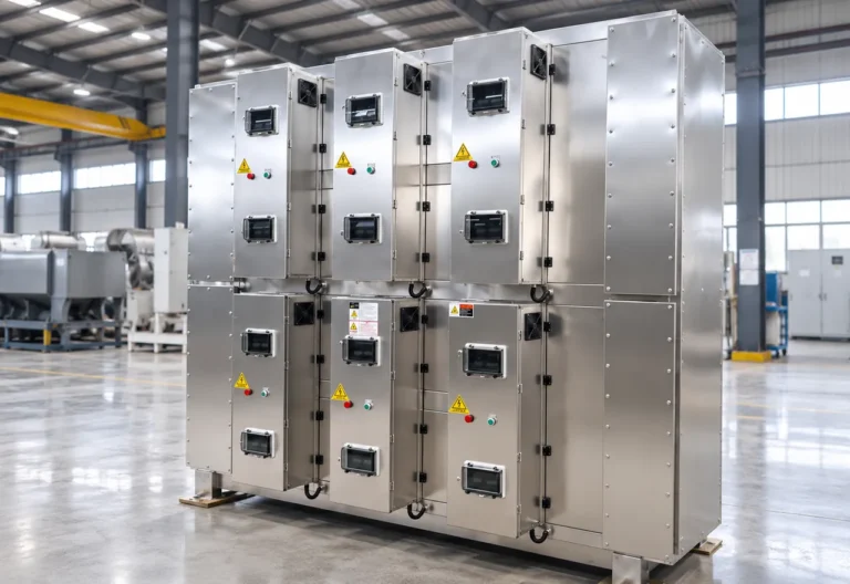
The Industrial Oil Fume Purification Equipment is designed to treat oil mist, fine aerosol, smoke and selected suspended particulate generated by industrial thermal and…
View Equipment →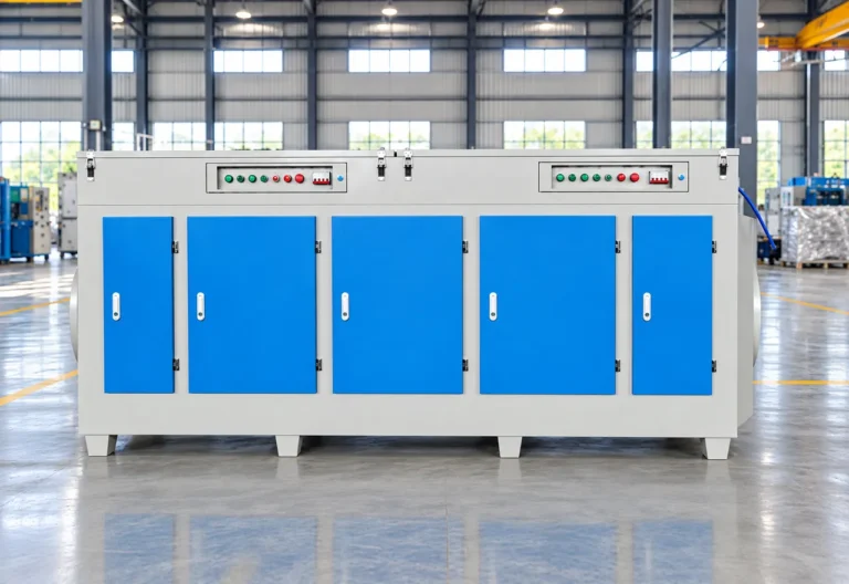
UV Photolysis Purification Equipment is designed for selected industrial exhaust streams containing odor compounds and gaseous organic contaminants.
View Equipment →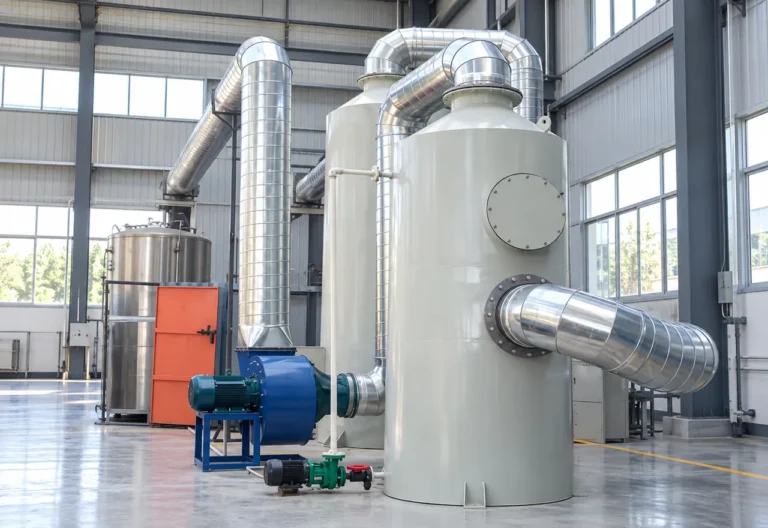
The BREM Water Spray Scrubber is a wet exhaust-treatment system designed to remove suitable particulate matter, soluble gaseous contaminants and selected acid or alkaline…
View Equipment →Send material, capacity, target output and site information for an application review.
You can also upload material photos, equipment images, plant layouts or technical documents.
You don't need to know all the technical details. Tell us what you're working with and what you want to achieve, and our team will help you determine the next step.